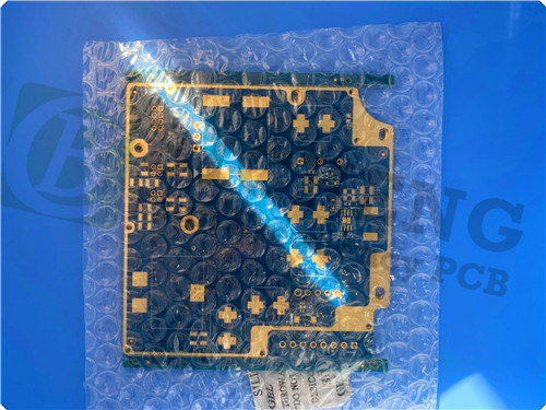
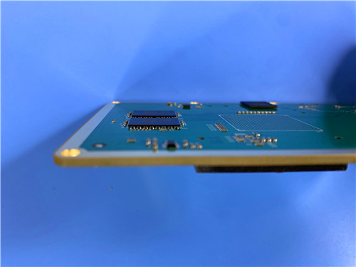
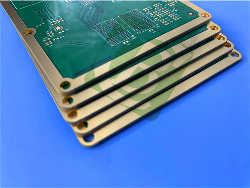
RO4003C + 370HR 10-Layer Hybrid PCB – Impedance Controlled & High Reliability Applications
1. Introduction to RO4003C + 370HR Hybrid PCB
RO4000® series hydrocarbon ceramic laminates are designed to offer superior high frequency performance and low cost circuit fabrication. The result is a low loss material which can be fabricated using standard epoxy/glass (FR-4) processes at competitive prices.
370HR is a high performance 180°C glass transition temperature (Tg) FR-4 system for multilayer Printed Wiring Board (PWB) applications where maximum thermal performance and reliability are required. This system provides improved thermal performance and low expansion rates in comparison to traditional FR-4 while retaining FR-4 processability.
This 10-layer hybrid PCB combines RO4003C for outer layers (high frequency signal integrity) and 370HR for inner layers (thermal reliability), offering exceptional electrical performance, impedance control, and mechanical stability for demanding RF, microwave, and high-speed digital applications.
2. Key Features of RO4003C
Dielectric constant of 3.38 ± 0.05 at 10 GHz (process) / 3.55 (design) Dissipation factor of 0.0027 at 10 GHz Thermal coefficient of dielectric constant (TCDk) of +40 ppm/°C Tg >280°C (TMA) Td of 425°C Low moisture absorption of 0.06% CTE (X/Y/Z): 11/14/46 ppm/°C Thermal conductivity of 0.71 W/(m·K) Compatible with standard FR-4 processing No specialized via preparation required
3. Key Features of 370HR
Tg of 180°C by DSC Td of 340°C (5% weight loss) T260 >60 min, T288 >30 min, T300 >2 min CTE (Z-axis pre-Tg): 45 ppm/°C, (post-Tg): 230 ppm/°C Z-axis expansion (50-260°C): 2.8% Dk of 4.04 @ 10 GHz, Df of 0.0250 @ 10 GHz Thermal conductivity of 0.4 W/(m·K) UL 94V-0 flammability rating Max operating temperature: 130°C
4. Benefits of RO4003C + 370HR Hybrid PCB
Combines high frequency performance (RO4003C) with thermal reliability (370HR) Standard FR-4 processing for both materials – no PTFE special handling Excellent dimensional stability for mixed dielectric multilayer constructions Low Z-axis CTE ensures reliable plated through-hole quality Impedance control ready for RF and high-speed digital designs Halogen-free option (370HR) for environmentally conscious designs Laser fluorescing and UV blocking for AOI compatibility
5. PCB Construction Details
| Item | Specification |
|---|
| Base material | RO4003C (outer cores) + 370HR FR-4 (inner cores) |
| Prepreg | RO4450F (for RO4003C bonding) + 370HR prepreg |
| Layer count | 10 layers |
| Board dimensions | 132mm x 144mm = 1PCS |
| Finished board thickness | 1.618 mm |
| Finished Cu weight | Outer layers: 1 oz (35 μm)
Inner layers (L3/L4/L7/L8): 0.5 oz (17 μm)
Inner layers (L5/L6): 1 oz (35 μm) |
| Surface finish | Immersion Gold (ENIG), 135%-150% thickness |
| Solder mask | Top: blue, white legend
Bottom: blue, white legend |
| Special features | Blind vias (L1-L2, L9-L10, L7-L10)
Resin plugging (resin filled vias)
Impedance control (50Ω, 80Ω) |
| Electrical test | 100% |
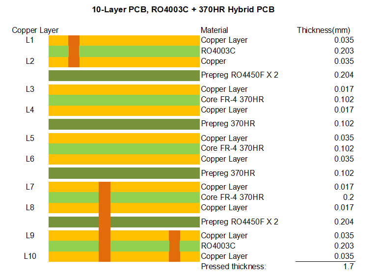
6. PCB Stackup (10-Layer Hybrid Rigid Structure)
L1 (Top Copper): 1 oz (0.035 mm) – 50Ω impedance trace: 12.2 mil width Core: RO4003C – 0.203 mm (8 mil) L2 (Inner Copper): 1 oz (0.035 mm) Prepreg: RO4450F ×2 – 0.204 mm L3 (Inner Copper): 0.5 oz (0.017 mm) – 80Ω diff pair: 3.5 mil trace / 5.5 mil spacing Core: 370HR FR-4 – 0.102 mm L4 (Inner Copper): 0.5 oz (0.017 mm) Prepreg: 370HR – 0.102 mm L5 (Inner Copper): 1 oz (0.035 mm) Core: 370HR FR-4 – 0.102 mm L6 (Inner Copper): 1 oz (0.035 mm) Prepreg: 370HR – 0.102 mm L7 (Inner Copper): 0.5 oz (0.017 mm) Core: 370HR FR-4 – 0.200 mm L8 (Inner Copper): 0.5 oz (0.017 mm) Prepreg: RO4450F ×2 – 0.204 mm L9 (Inner Copper): 1 oz (0.035 mm) Core: RO4003C – 0.203 mm (8 mil) L10 (Bottom Copper): 1 oz (0.035 mm)
Total Pressed Thickness: 1.618 mm (1.7 mm nominal)
7. Impedance Control Specifications
| Layer | Impedance | Trace Width | Spacing | Target |
|---|
| L1 (Top) | 50 Ω (single-ended) | 12.2 mil | – | ±10% |
| L3 | 80 Ω (differential) | 3.5 mil | 5.5 mil | ±10% |
8. PCB Special Features
Blind Vias: L1-L2, L9-L10, L7-L10 Through Holes: Full stack Resin Plugging: All vias resin filled and capped Asymmetric Copper: L5/L6 1 oz, L3/L4/L7/L8 0.5 oz Impedance Control: 50Ω and 80Ω controlled lines
9. Primary Application Areas
RF and microwave circuits High-speed digital designs Base station and telecom equipment Automotive radar and sensors Satellite communication systems Point-to-point digital radio High reliability industrial controls Backplanes and multilayer motherboards
10. Quality Assurance
Artwork supplied: Gerber RS-274-X Accepted standard: IPC-Class-2 (typical) Availability: Worldwide RO4003C compliant with IPC-4103/10 370HR compliant with IPC-4101E Type /127, /128, /130
11. RO4003C High Frequency Laminate Introduction
RO4000 hydrocarbon ceramic laminates are designed to offer superior high frequency performance and low cost circuit fabrication. The result is a low loss material which can be fabricated using standard epoxy/glass (FR-4) processes at competitive prices.
RO4003C material possesses the properties needed by designers of RF microwave circuits, matching networks, and controlled impedance transmission lines. Low dielectric loss allows RO4003C to be used in many applications where higher operating frequencies limit the use of conventional circuit board laminates. The temperature coefficient of dielectric constant is among the lowest of any circuit board material, and the dielectric constant is stable over a broad frequency range.
RO4003C's thermal coefficient of expansion (CTE) is similar to that of copper, providing excellent dimensional stability and reliable plated through-hole quality, even in severe thermal shock applications. RO4003C has a Tg of >280°C, so its expansion characteristics remain stable over the entire range of circuit processing temperatures.
RO4003C laminates can easily be fabricated into printed circuit boards using standard FR-4 circuit board processing techniques. Unlike PTFE based high performance materials, RO4003C does not require specialized via preparation processes such as sodium etch.
12. 370HR High Performance Laminate Introduction
370HR is a high performance 180°C glass transition temperature (Tg) FR-4 system for multilayer Printed Wiring Board (PWB) applications where maximum thermal performance and reliability are required. 370HR laminate and prepreg products are manufactured with a unique high performance multifunctional epoxy resin, reinforced with electrical grade (E-glass) glass fabric.
This system provides improved thermal performance and low expansion rates in comparison to traditional FR-4 while retaining FR-4 processability. In addition to this superior thermal performance, the mechanical, chemical and moisture resistance properties all equal or exceed the performance of traditional FR-4 materials.
The 370HR system is also laser fluorescing and UV blocking for maximum compatibility with Automated Optical Inspection (AOI) systems, optical positioning systems and photoimagable solder mask imaging. 370HR has proven to be best in class for sequential lamination designs.
13. RO4003C Data Sheet
| Property | Typical Value | Units | Conditions | Test Method |
|---|
| Dk (process) | 3.38 ± 0.05 | – | 10 GHz / 23°C | IPC-TM-650 2.5.5.5 |
| Dk (design) | 3.55 | – | 8-40 GHz | Differential Phase Length |
| Df | 0.0027 | – | 10 GHz / 23°C | IPC-TM-650 2.5.5.5 |
| TCDk | +40 | ppm/°C | -50 to 150°C | IPC-TM-650 2.5.5.5 |
| Volume Resistivity | 1.7 × 10¹⁰ | MΩ·cm | COND A | IPC-TM-650 2.5.17.1 |
| Surface Resistivity | 4.2 × 10⁹ | MΩ | COND A | IPC-TM-650 2.5.17.1 |
| Electrical Strength | 31.2 (780) | kV/mm (V/mil) | 0.51 mm | IPC-TM-650 2.5.6.2 |
| Tensile Modulus (X/Y) | 19,650 / 19,450 | MPa (ksi) | RT | ASTM D638 |
| Tensile Strength (X/Y) | 139 / 100 | MPa (ksi) | RT | ASTM D638 |
| Flexural Strength | 276 (40) | MPa (kpsi) | – | IPC-TM-650 2.4.4 |
| Dimensional Stability | <0.3 | mm/m | after etch + E2/150°C | IPC-TM-650 2.4.39A |
| CTE (X/Y/Z) | 11 / 14 / 46 | ppm/°C | -55 to 288°C | IPC-TM-650 2.4.41 |
| Tg | >280 | °C TMA | A | IPC-TM-650 2.4.24.3 |
| Td | 425 | °C TGA | – | ASTM D3850 |
| Thermal Conductivity | 0.71 | W/(m·K) | 80°C | ASTM C518 |
| Moisture Absorption | 0.06 | % | 48 hrs immersion | ASTM D570 |
| Density | 1.79 | g/cm³ | 23°C | ASTM D792 |
| Copper Peel Strength | 1.05 (6.0) | N/mm (pli) | after solder float | IPC-TM-650 2.4.8 |
| Lead-Free Compatible | Yes | – | – | – |
14. 370HR Data Sheet
| Property | Typical Value | Units | Conditions | Test Method |
|---|
| Tg (DSC) | 180 | °C | – | IPC-TM-650 2.4.25 |
| Td (5% wt loss) | 340 | °C | – | ASTM D3850 |
| T260 | >60 | min | – | ASTM D3850 |
| T288 | >30 | min | – | ASTM D3850 |
| CTE (Z-axis pre-Tg) | 45 | ppm/°C | – | IPC-TM-650 2.4.24 |
| CTE (Z-axis post-Tg) | 230 | ppm/°C | – | IPC-TM-650 2.4.24 |
| CTE (X-axis pre/post) | 13 / 14 | ppm/°C | – | IPC-TM-650 2.4.24 |
| CTE (Y-axis pre/post) | 14 / 17 | ppm/°C | – | IPC-TM-650 2.4.24 |
| Z-axis Expansion (50-260°C) | 2.8 | % | – | IPC-TM-650 2.4.24 |
| Thermal Conductivity | 0.4 | W/(m·K) | – | ASTM D5930 |
| Dk @ 10 GHz | 3.92 | – | 50% resin | IPC-TM-650 2.5.5.9 |
| Df @ 10 GHz | 0.0250 | – | 50% resin | IPC-TM-650 2.5.5.9 |
| Volume Resistivity | 3.0 × 10⁸ | MΩ·cm | after moisture | IPC-TM-650 2.5.17.1 |
| Surface Resistivity | 3.0 × 10⁶ | MΩ | after moisture | IPC-TM-650 2.5.17.1 |
| Dielectric Breakdown | >50 | kV | – | IPC-TM-650 2.5.6 |
| Electric Strength | 54 (1350) | kV/mm (V/mil) | – | IPC-TM-650 2.5.6.2 |
| Peel Strength (low profile) | 1.14 (6.5) | N/mm (lb/in) | after thermal stress | IPC-TM-650 2.4.8 |
| Flexural Strength (LW/CW) | 90,000 / 77,000 | lb/in² | – | IPC-TM-650 2.4.4 |
| Moisture Absorption | 0.15 | % | – | IPC-TM-650 2.6.2.1 |
| Flammability | V-0 | Rating | – | UL 94 |
| Max Operating Temperature | 130 | °C | UL Cert | – |
15. Typical Applications
RF and microwave circuits High-speed digital designs Base station and telecom equipment Automotive radar and sensors Satellite communication systems Point-to-point digital radio High reliability industrial controls Backplanes and multilayer motherboards Sequential lamination designs Power amplifiers and filters
16. Standard Thicknesses, Panel Sizes & Claddings
RO4003C Standard Thicknesses
| Thickness (inch) | Thickness (mm) | Tolerance |
|---|
| 0.008" | 0.203 mm | ±0.0010" |
| 0.012" | 0.305 mm | ±0.0010" |
| 0.016" | 0.406 mm | ±0.0015" |
| 0.020" | 0.508 mm | ±0.0015" |
| 0.032" | 0.813 mm | ±0.0020" |
| 0.060" | 1.524 mm | ±0.0040" |
Standard Panel Sizes
24" × 18" (610 mm × 457 mm) 24" × 21" (610 mm × 533 mm) 24" × 36" (610 mm × 915 mm) 48" × 36" (1219 mm × 915 mm)
Standard Claddings
|